
This is part 2 of a seven part series which explores some of the issues around zero carbon vehicles and which future technologies might be best for HGVs to avoid carbon emissions. The seven parts parts are:
- Understanding the Typical Power Requirements of an HGV
- Basic Designs of Diesel, Battery and Fuel Cell Powertrains (this post)
- Comparing Diesel, Battery and Fuel Cell Powertrains
- Assessing Future Manufacturing Costs of Diesel, Battery and Fuel Cell Powertrains for HGVs
- Costs of Hydrogen Fuel / Building A Hydrogen & Electric Charging Infrastructure
- Commercial Viability of Operating A Battery or Fuel Cell Powertrain HGV
- Summary, A Look at Developments Which May Help Achievement of Zero Carbon In-use HGVs.
Part 2: Basic Designs of Diesel, Battery and Fuel Cell Powertrains
In Part 2 we present basic designs of diesel, electric battery and hydrogen fuel cell powertrains that could power an Heavy Goods Vehicle (HGV).
2.1 Diesel Power Basic Design
Figure 3 shows the main components of a diesel powertrain. Diesel powertrains are well established and dominate the HGV market. More recent developments have been in the exhaust treatments to reduce NOx and other harmful emissions.
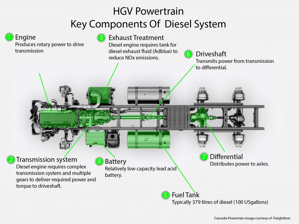
Growth in the UK HGV fleet size, primarily powered by diesel, is projected to outweigh incremental improvements in vehicle fuel efficiency. In 2015 HGVs generated 19.6 MtCO2e of Greenhouse Gases (GHG), 5.3% higher than in 2010 (Department for Transport 2017a, 2017b). The UK (and the rest of the world) has issues with HGV GHG and pollutant emissions which are unlikely to be overcome using diesel engine technology. Both battery and fuel cell technology have the potential for zero carbon and pollutant emissions in-use, which is why they are both attracting significant interest for use in powering HGVs
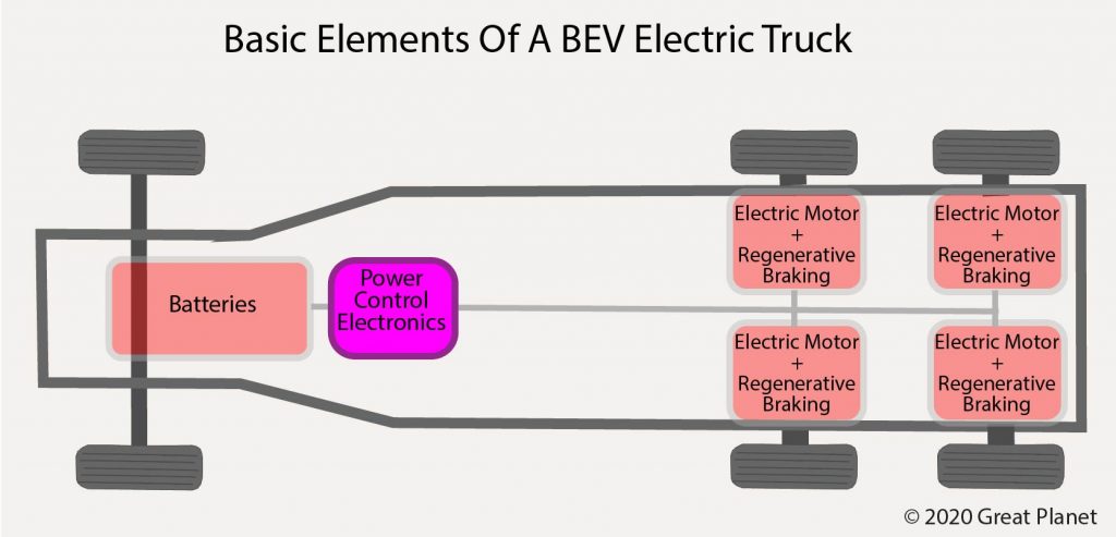
2.2 Battery Electric Vehicles (BEVs) & Hydrogen Fuel Cell Electric Vehicles (FCEVs) Basic Design
Figures 4 & 5 show the basic elements of a BEV and an Hydrogen FCEV. Both technologies require:
- Storage batteries (commonly lithium ion)
- Power control electronics
- Electric motors with regenerative braking
The basic difference is that a BEV is powered by batteries usually charged from the electricity grid. A FCEV uses a fuel cell to combine hydrogen (from an on-board storage tank) and oxygen (from the air) to produce water and electricity. The electricity is used to power electric motors or stored in a battery for later use.
The key component differences are in the size of the battery used and that the FCEV requires hydrogen storage tanks along with a fuel cell and coolant and air sub-systems. A BEV will have a shorter range than a FCEV and will take longer to charge (hours). With sufficient hydrogen storage a FCEV is capable of driving 800-1,500 km before needing to refuel. Full refuelling would take around 30 minutes.
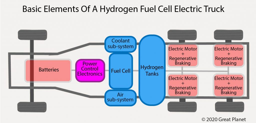
An important point that is not always appreciated in some of the discussion about BEVs and FCEVs is that there are a number of common components between them. Developments in battery technology, power control electronics and electric motors will benefit both design types.
2.3 Fuel Cell Basics
A fuel cell takes fuel (such as hydrogen, methane or methanol) and oxygen and uses an electrochemical process to generate DC electricity. Water and exhaust gases are also produced as waste. When hydrogen gas is used as the fuel, water is produced with no harmful pollutants or greenhouse gases.
Figure 6 illustrates the main subsystems of a hydrogen fuel cell system. A number of individual fuel cells are built into a fuel stack, based on the overall desired power output. To operate the fuel cell system, and generate electricity to drive an electrical load, the fuel stack needs subsystems for controlling the hydrogen gas supply, the air supply and to keep the fuel cell stack at the right temperature. These subsystems are referred to as the Balance of Plant (BoP). A hydrogen storage tank is also required.
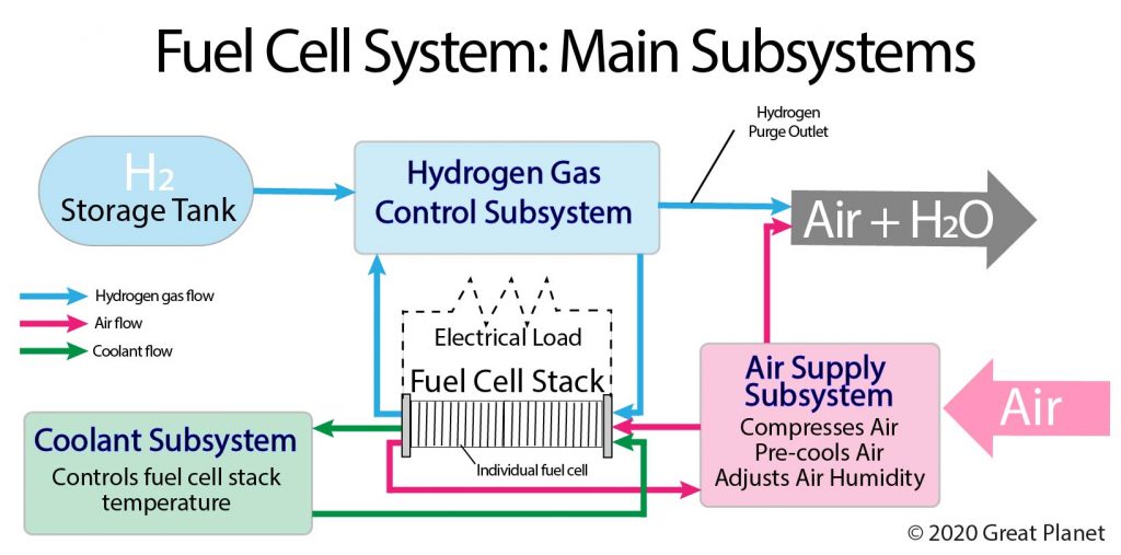
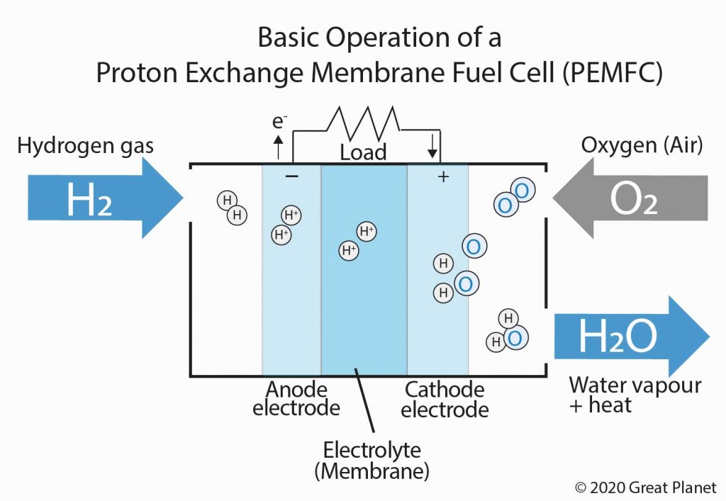
Proton Exchange Membrane Fuel Cells (PEMFCs) are generally considered for transport applications as use with hydrogen fuel results in zero carbon emissions, they have an excellent dynamic response to power demand and a fast start-up time. Figure 7 illustrates the basic operation of a PEMFC using hydrogen gas, along with oxygen from the air, to drive an electrical load. It produces water and oxygen depleted air from the exhaust.
References
Department for Transport (2017a). Transport Statistics Great Britain 2017 [online] Available at https://assets.publishing.service.gov.uk/government/uploads/system/uploads/attachment_data/file/6
64323/tsgb-2017-print-ready-version.pdf [Accessed 28 August 2018]
Department for Transport (2017b). Vehicle licensing statistics: 2017 [online] Available at https://www.gov.uk/government/statistics/vehicle-licensing-statistics-2017 [Accessed 28 August 2018]
Leave a Reply